Write Field Import – TXT Format Specification
To download this documentation as a PDF, click here.
Introduction
Write fields can be imported directly into Beamfox Proximity using a text file with a .txt extension. This document explains the format used to generate write fields and alignment markers in such a file.
A file consists of a number of statements separated by new lines. A statement can either define one or more write fields, the global marks, or a single local mark. Each statement consists of the statement type command followed by a number of arguments separated by comma:
COMMAND, argument_1, argument_2, ...Spaces and empty lines in the file are ignored. At least one write field must be defined for the file to be valid.
For advanced users
The content in this section is not strictly necessary for understanding the basic functionality of the format, and can therefore be skipped at the readers discretion. It can, however, provide valuable insights for users with more advanced use cases.
Splitting of geometries into write fields
Before running proximity effect correction, Beamfox Proximity will first check for geometries that lie either fully or partially outside of any write fields. Geometries that are partially outside are split at the edge of the write field, after which all geometries that lie outside of any write fields are discarded.
During proximity effect correction, Beamfox Proximity will fracture all geometries based on dose, user settings, and existing fractures. The resulting geometries are then assigned to write fields.
The geometries will be assigned to the first write field in which the geometry can be entirely contained. The first write field depends on the writing order, which is determined by the order in the write field file. For arrays, the write fields are written one row at a time. If a geometry cannot be fully contained within a single write field, the geometry will be split at edge of the first write field. The two parts of the newly-split geometries are both considered new geometries, and go through the same process again. This process continues until all geometries have been assigned to write fields.
Autofill fields capture and split geometries similarly to write fields.
For write fields with multi-pass enabled, a geometry will only be captured by the resulting effective write field. In other words, a geometry will only be captured if it is placed within the area that is overlapped by all multi-pass passes.
Virtual and physical write fields
It is possible to use write fields in Beamfox Proximity (virtual write fields) that are smaller than the actual write fields used by the e-beam system (physical write fields). This can potentially improve the quality and fidelty of the exposure, as this ensures writing will only occur in the central part of the physical write field, which reduces errors caused by defocus and astigmatism. The physical write field size is assumed to be the largest write field size specified. The number of dots is read from the same statement where the physical write field size is declared – all other number of dots declarations are ignored.
Multi-pass mode
Geometries in the design that cross the interface between separate write fields are susceptible to stitching errors, caused by small offsets being introduced when the e-beam system moves from one write field to the next. This effect can be minimized at the expense of a slightly increased writing time by using multi-pass mode.
In multi-pass mode, geometries are written multiple times using a fraction of the dose with a slight offset each time. More specifically, the geometries are written passes number of times with a dose of 1 / passes. The offset between each pass is defined by a displacement distance of shift, and an angle of \phi_0 + \frac{2n + 1}{N}\pi relative to the x-axis, where n is the pass id running from 0 to N - 1 , \phi = rotation, and N = passes.
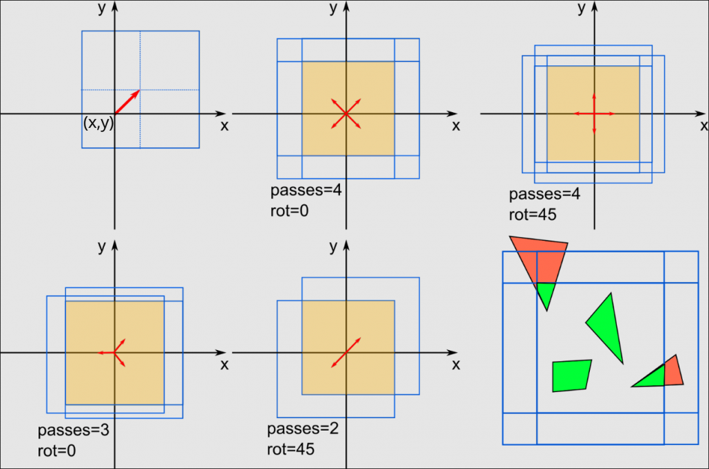
Note: Beamfox Proximity will display the effective write field instead of all the individual multi-pass write fields. This results in a virtual write field that is smaller than the specified size.
Write Field Statements
A write field statement can either define a single write field or an array of
write fields. The write field statement commands are CHIP, MCHIP, ARRAY,
MARRAY, SARRAY, and MSARRAY.
For arrays, the primary and secondary array vectors are used to define array direction. The primary array vector specifies displacement between columns, and the secondary array vector specifies the displacement between rows. The primary and secondary array vectors cannot be parallel.
CHIP
Defines a single write field. The signature of the statement is:
CHIP, x, y, size, dots
| Name | Type | Conditions | Description |
|---|---|---|---|
x | real | – | The x-coordinate of the center of the write field. |
y | real | – | The y-coordinate of the center of the write field. |
size | real | size > 0 | The width of the write field in micrometers. |
dots | integer | dots > 0 | The number of dots along each axis of the write field. |
Example:
CHIP, 259.9, 255, 500, 1000000See example CHIP.txt for a full example.
MCHIP
Defines a single multi-pass write field. The signature of the statement is:
MCHIP, x, y, size, dots, passes, shift, rotation
| Name | Type | Conditions | Description |
|---|---|---|---|
x | real | – | The x-coordinate of the center of the write field. |
y | real | – | The y-coordinate of the center of the write field. |
size | real | size > 0 | The width of the write field in micrometers. |
dots | integer | dots > 0 | The number of dots along each axis of the write field. |
passes | integer | passes > 1 | The number of write fields to use for multi-passing. |
shift | real | shift > 0 | The distance to displace each write field in micrometers. |
rotation | real | – | The offset angle of the displacement direction. |
Example:
MCHIP, 259.9, 255, 500, 1000000, 3, 100, 0See example MCHIP.txt for a full example.
ARRAY
Defines an array of write fields. The signature of the statement is:
ARRAY, columns, rows, x, y, size, dots, ax, ay, bx, by
| Name | Type | Conditions | Description |
|---|---|---|---|
columns | integer | columns > 0 | The number of columns in the array. |
rows | integer | rows > 0 | The number of rows in the array. |
x | real | – | The x-coordinate of the center of the first write field. |
y | real | – | The y-coordinate of the center of the first write field. |
size | real | size > 0 | The width of the write field in micrometers. |
dots | integer | dots > 0 | The number of dots along each axis of the write field. |
ax | real | – | The x-component of the primary array vector. |
ay | real | – | The y-component of the primary array vector. |
bx | real | – | The x-component of the secondary array vector. |
by | real | – | The y-component of the secondary array vector. |
Example:
ARRAY, 2, 2, 259.9, 255, 500, 1000000, 200, 200, 0, 400See example ARRAY.txt for a full example.
MARRAY
Defines an array of multi-pass write fields. The signature of the statement is:
MARRAY, columns, rows, x, y, size, dots, ax, ay, bx, by,
passes, shift, rotation
| Name | Type | Conditions | Description |
|---|---|---|---|
columns | integer | columns > 0 | The number of columns in the array. |
rows | integer | rows > 0 | The number of rows in the array. |
x | real | – | The x-coordinate of the center of the first write field. |
y | real | – | The y-coordinate of the center of the first write field. |
size | real | size > 0 | The width of the write field in micrometers. |
dots | integer | dots > 0 | The number of dots along each axis of the write field. |
ax | real | – | The x-component of the primary array vector. |
ay | real | – | The y-component of the primary array vector. |
bx | real | – | The x-component of the secondary array vector. |
by | real | – | The y-component of the secondary array vector. |
passes | integer | passes > 1 | The number of write fields to use for multi-passing. |
shift | real | shift > 0 | The distance to displace each write field in micrometers. |
rotation | real | – | The offset angle of the displacement direction. |
Example:
MARRAY, 2, 2, 259.9, 255, 500, 1000000, 200, 200, 0, 400, 3, 100, 0See example MARRAY.txt for a full example.
SARRAY
Defines a grid of write fields where the write fields’ edges touch, starting from the lower left to upper right. The signature of the statement is:
SARRAY, columns, rows, x, y, size, dots
| Name | Type | Conditions | Description |
|---|---|---|---|
columns | integer | columns > 0 | The number of columns in the array. |
rows | integer | rows > 0 | The number of rows in the array. |
x | real | – | The x-coordinate of the center of the bottom left write field |
y | real | – | The y-coordinate of the center of the bottom left write field |
size | real | size > 0 | The width of the write field in micrometers. |
dots | integer | dots > 0 | The number of dots along each axis of the write field. |
Example:
SARRAY, 2, 2, 259.9, 255, 500, 1000000See example SARRAY.txt for a full example.
MSARRAY
Defines a grid of multi-pass write fields where the edges of the effective write fields touch, starting from the lower left to upper right. The signature of the statement is:
MSARRAY, columns, rows, x, y, size, dots, passes, shift,
rotation
| Name | Type | Conditions | Description |
|---|---|---|---|
columns | integer | columns > 0 | The number of columns in the array. |
rows | integer | rows > 0 | The number of rows in the array. |
x | real | – | The x-coordinate of the center of the bottom left write field |
y | real | – | The y-coordinate of the center of the bottom left write field |
size | real | size > 0 | The width of the write field in micrometers. |
dots | integer | dots > 0 | The number of dots along each axis of the write field. |
passes | integer | passes > 1 | The number of write fields to use for multi-passing. |
shift | real | shift > 0 | The distance to displace each write field. |
rotation | real | – | The offset angle of the displacement direction. |
Example:
MSARRAY, 2, 2, 259.9, 255, 500, 1000000, 3, 100, 0See example MSARRAY.txt for a full example.
Global Mark Statements
A global mark statement defines all the global markers of the chip.
Only one global mark statement is allowed per file.
A global mark statement can define 1-4 points.
MARK1
Defines a single global mark. The signature of the statement is:
MARK1, x, y
| Name | Type | Conditions | Description |
|---|---|---|---|
x | real | – | The x-coordinate of the mark. |
y | real | – | The y-coordinate of the mark. |
Example:
MARK1, -40.1, -45See example MARK1.txt for a full example.
MARK2
Defines two global marks. The signature of the statement is:
MARK2, x0, y0, x1, y1
| Name | Type | Conditions | Description |
|---|---|---|---|
x0 | real | – | The x-coordinate of the first mark. |
y0 | real | – | The y-coordinate of the first mark. |
x1 | real | – | The x-coordinate of the second mark. |
y1 | real | – | The y-coordinate of the second mark. |
MARK3
Defines three global marks. The signature of the statement is:
MARK3, x0, y0, x1, y1, x2, y2
| Name | Type | Conditions | Description |
|---|---|---|---|
x0 | real | – | The x-coordinate of the first mark. |
y0 | real | – | The y-coordinate of the first mark. |
x1 | real | – | The x-coordinate of the second mark. |
y1 | real | – | The y-coordinate of the second mark. |
x2 | real | – | The x-coordinate of the third mark. |
y2 | real | – | The y-coordinate of the third mark. |
MARK4
Defines four global marks. The signature of the statement is:
MARK3, x0, y0, x1, y1, x2, y2, x3, y3
| Name | Type | Conditions | Description |
|---|---|---|---|
x0 | real | – | The x-coordinate of the first mark. |
y0 | real | – | The y-coordinate of the first mark. |
x1 | real | – | The x-coordinate of the second mark. |
y1 | real | – | The y-coordinate of the second mark. |
x2 | real | – | The x-coordinate of the third mark. |
y2 | real | – | The y-coordinate of the third mark. |
x3 | real | – | The x-coordinate of the fourth mark. |
y3 | real | – | The y-coordinate of the fourth mark. |
Example:
MARK4, -40.1, -45, -40.1, 555, 559.9, 555, 559.9, -45See example MARK4.txt for a full example.
Local Mark Statement
A local mark statement defines the location of a local marker.
One marker is defined per statement and there is no limit on the number of statements.
MARKL
Defines a local marker. The signature of the statement is:
MARKL, x, y
| Name | Type | Conditions | Description |
|---|---|---|---|
x | real | – | The x-coordinate of the mark. |
y | real | – | The y-coordinate of the mark. |
Example:
MARKL, 559.9, 555See example MARKL.txt for a full example.
Examples
CHIP.txt
Create a write field with center in (259.9, 255), width 500 micrometers, and 1 million dots.
CHIP, 259.9, 255, 500, 1000000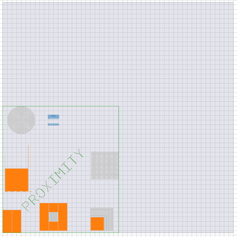
MCHIP.txt
Create a multi-pass write field with center in (259.9, 255), width 500 micrometers, and 1 million dots. The write field will be written with three passes, a displacement of 100 micrometers, and no rotation offset.
MCHIP, 259.9, 255, 500, 1000000, 3, 100, 0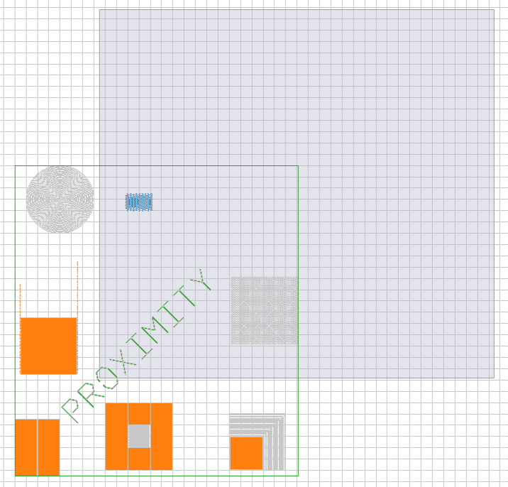
ARRAY.txt
Create a 2 x 2 array of write fields, with the first write field’s center in (259.9, 255). Each write field has a width of 500 micrometers and 1 million dots. Each column will be shifted by (200, 200) micrometers, and each row will be shifted by (0, 400) micrometers.
ARRAY, 2, 2, 259.9, 255, 500, 1000000, 200, 200, 0, 400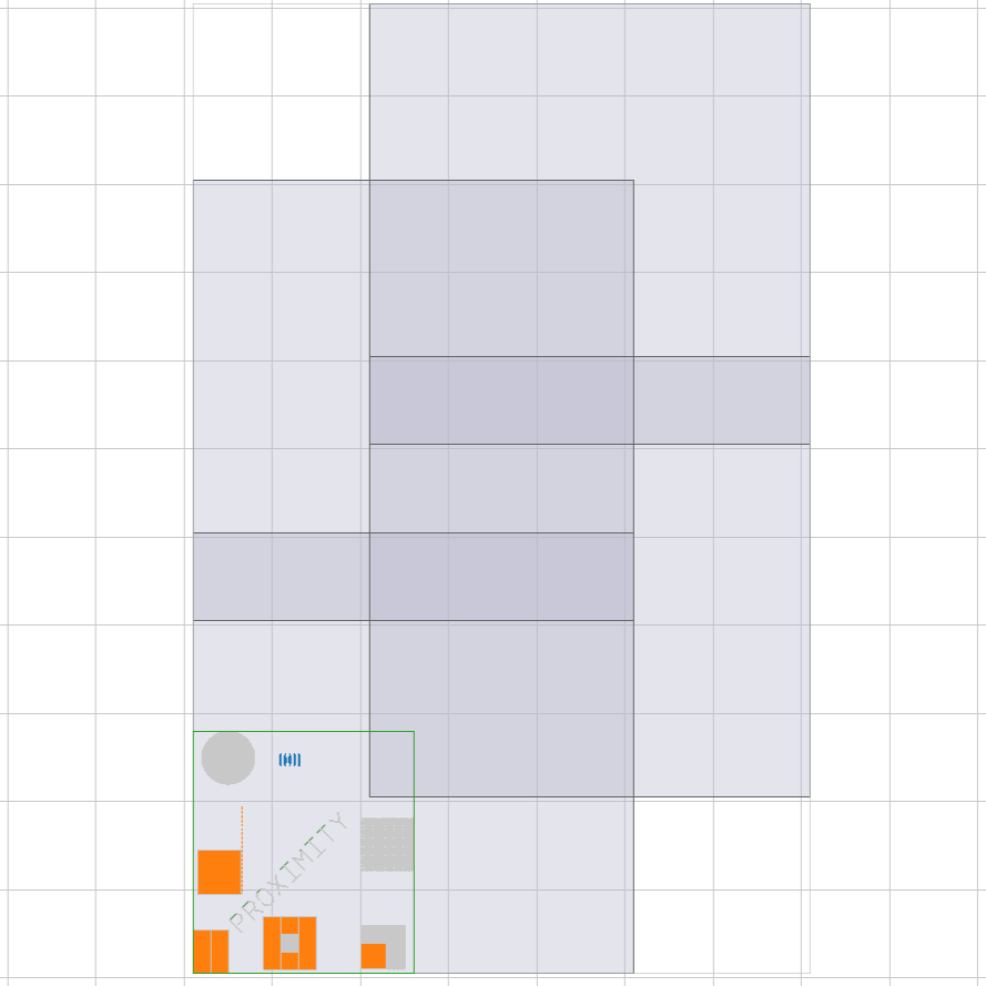
MARRAY.txt
Create a 2 x 2 array of multi-pass write fields, with the first write field’s center in (259.9, 255). Each write field has a width of 500 micrometers and 1 million dots. Each column will be shifted by (200, 200) micrometers, and each row will be shifted by (0, 400) micrometers.. Each write field will be written with three passes, a displacement of 100 micrometers, and no rotation.
MARRAY, 2, 2, 259.9, 255, 500, 1000000, 200, 200, 0, 400, 3, 100, 0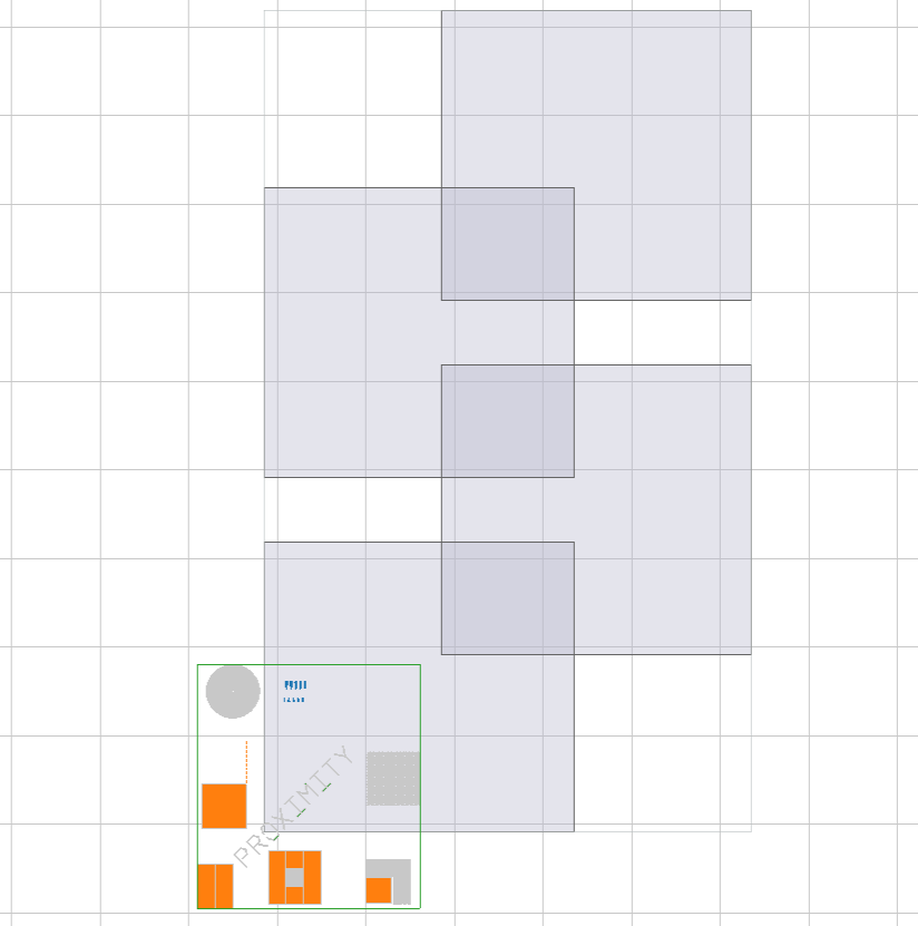
SARRAY.txt
Create a 2 x 2 array of write fields in a grid, starting from a write field in the lower left corner with center in (259.9, 255). Each write field has a width of 500 micrometers and 1 million dots.
SARRAY, 2, 2, 259.9, 255, 500, 1000000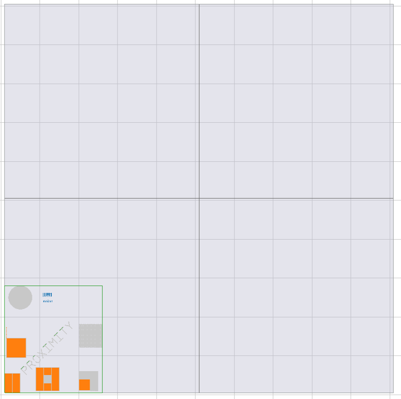
MSARRAY.txt
Create a 2 x 2 array of multi-pass write fields in a grid, starting from a write field in the lower left corner with center in (259.9, 255). Each write field has a width of 500 micrometers and 1 million dots. Each write field will be written with three passes, a displacement of 100 micrometers, and no rotation.
MSARRAY, 2, 2, 259.9, 255, 500, 1000000, 3, 100, 0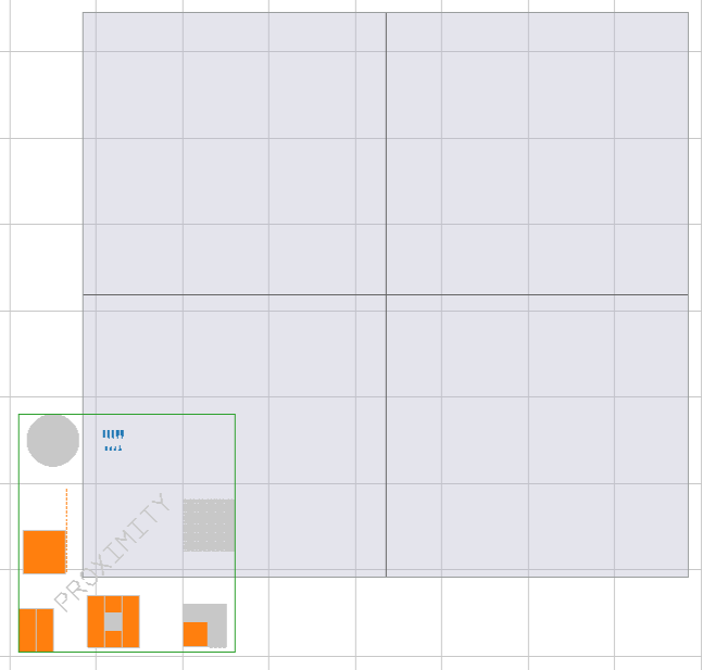
MARK1.txt
Define a single global mark with coordinates (-40.1, -45).
CHIP, 259.9, 255, 500, 1000000
MARK1, -40.1, -45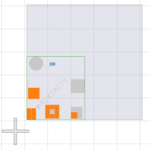
MARK4.txt
Define four global marks with coordinates of (-40.1, -45), (-40.1, 555), (555.9, 555) and (559.9, -45), respectively.
CHIP, 259.9, 255, 500, 1000000
MARK4, -40.1, -45, -40.1, 555, 559.9, 555, 559.9, -45
MARKL.txt
Define two local markers with coordinates (-40.1, -45) and (559.9, 555), respectively, using two separate local mark statements.
CHIP, 259.9, 255, 500, 1000000
MARKL, -40.1, -45
MARKL, 559.9, 555
To download this documentation as a PDF, click here.