Write Field Import – YAML Format Specification
To download this documentation as a PDF, click here.
Introduction
Write fields can be imported directly into Beamfox Proximity using a YAML file with a .yaml extension. This document explains the format used to generate write fields and alignment markers in such a file.
YAML Basics
At its core, files written in YAML primarily consist of key-value pairs, which in this documentation will be referred to as statements. Statements in YAML files contain an indentifier (the key) and the associated value, separated by a colon and space. Statements are separated by new lines. Some example statements are:
company-name: "Beamfox Technologies"
pi: 3.14159
is-it-friday: true
In YAML, indentation is used to denote structure/nesting. YAML does not allow
the use of tabs, and instead, spaces are used. There is no requirement to the
number of spaces used to indent, as long as it is consistent throughout the
document. In the example below, some properties of an animal is defined:
animal:
   type: "Fox"
   legs: 4
   has-tail: true
Here, the statements type, legs, and has-tail “belong” to the animal
statement due to their indentation. YAML supports values of primitive datatypes
(integers, strings, etc.), but also more complex data structure objects. Such
objects can in themselves be understood as collections of statements. In the
example above, animal does not take a primitive datatype (e.g., an integer),
but instead takes a data object that consists of the statements type, legs,
has-tail, and possibly more. Some statements may be required or optional,
depending on the type of object or other factors such as the inclusion of other
statements.
YAML also supports lists, which are defined using hyphens, where a hyphen indicates a new element in the list. Expanding on the previous example:
animal:
   type: "Fox"
   legs: 4
   has-tail: true
   diet:
      - "Rodents"
      - "Birds"
      - "Berries"
      - "Fruits"
This list with four elements is contained within the diet statement, which itself is contained within the animal statement.
YAML statement keys are case sensitive, while statement values that are strings,
such as the values of type and the list members of diet, are not.
For more information about the YAML language, see https://en.wikipedia.org/wiki/YAML.
Creating write fields
To create write fields, the YAML file should contain a combination of global
statements, WriteField statements, and others. The statement fields,
detailed further below, contains a list of WriteField objects. New write fields
(or write field lattices) can be created by adding WriteField objects to this
list, which in YAML is done with hyphens. For example, a single write field of
width 500 micrometers and 1 million dots, with center in (250, 250), can be
created with:
size: 500
dots: 1000000
fields:
 - origin:
    x: 250
    y: 250
The origin statement is a required statement of the WriteField object and
specifies the center coordinates of the write field. Note, that the x and y
statements relate to the origin statement, and must therefore be nested within
this statement.
Another write field with center in (750, 750) can be added by adding another WriteField object to the list:
size: 500
dots: 1000000
fields:
  - origin:
     x: 250
     y: 250
  - origin:
     x: 750
     y: 750
We can add further properties to each write field by adding further statements supported in the WriteField object. Expanding on the previous example, the size of the first write field size is here changed to 300 micrometers, and the pitch (beam step size) is changed to 2 in the second write field:
size: 500
dots: 1000000
fields:
  - origin:
     x: 250
     y: 250
    size: 300
  - origin:
     x: 750
     y: 750
    pitch: 2
Note that the indentation of these added statements must match the indentation
level of the origin statement, as they are all WriteField statements that
refer to the same WriteField object.
E-beam system compability
The YAML write field file is designed to be universal, and therefore independent of different e-beam systems, which may have different settings or feature sets. When loading a write field file into the Beamfox Proximity application and running proximity effect correction, the application will ensure that the specified write fields and their properties are compatible with the selected output file format. Therefore, if the YAML file contains statements and/or statement values that are not compatible with the selected output file format, these will be ignored or converted as best possible, or an error is produced.
For advanced users
The content in this section is not strictly necessary for understanding the basic functionality of the format, and can therefore be skipped at the readers discretion. It can, however, provide valuable insights for users with more advanced use cases.
Virtual and physical write fields
It is possible to use write fields in Beamfox Proximity (virtual write fields)
that are smaller than the actual write fields used by the e-beam system
(physical write fields). This can potentially improve the quality and fidelty of
the exposure, as this ensures writing will only occur in the central part of the
physical write field, which reduces errors caused by defocus and astigmatism.
The physical write field size is specified using the global size statement.
The virtual write field size is specified using the size statement for
individual WriteField objects.
Multi-pass mode
Geometries in the design that cross the interface between separate write fields are susceptible to stitching errors, caused by small offsets being introduced when the e-beam system moves from one write field to the next. This effect can be minimized at the expense of a slightly increased writing time by using multi-pass mode.
In multi-pass mode, geometries are written multiple times using a fraction of the dose with a slight offset each time. More specifically, the geometries are written passes number of times with a dose of 1 / passes. The offset between each pass is defined by a displacement distance of shift, and an angle of \phi_0 + \frac{2n + 1}{N}\pi relative to the x-axis, where n is the pass id running from 0 to N - 1 , \phi = rotation, and N = passes.
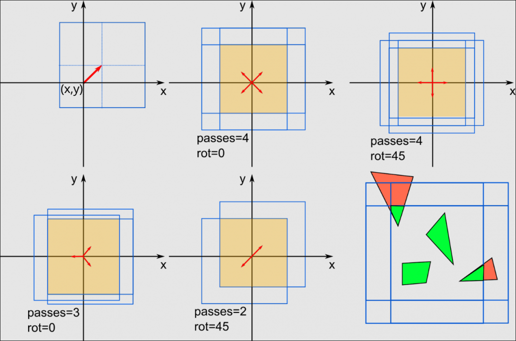
Note: Beamfox Proximity will display the effective write field instead of all the individual multi-pass write fields. This results in a virtual write field that is smaller than the specified size.
Splitting of geometries into write fields
Before running proximity effect correction, Beamfox Proximity will first check for geometries that lie either fully or partially outside of any write fields. Geometries that are partially outside are split at the edge of the write field, after which all geometries that lie outside of any write fields are discarded.
During proximity effect correction, Beamfox Proximity will fracture all geometries based on dose, user settings, and existing fractures. The resulting geometries are then assigned to write fields.
The geometries will be assigned to the first write field in which the geometry
can be entirely contained. The first write field depends on the writing order,
which is determined by the order in the YAML file. For lattices, the order is
defined by write_mode. If a geometry cannot be fully contained within a single
write field, the geometry will be split at edge of the first write field. The
two parts of the newly-split geometries are both considered new geometries, and
go through the same process again. This process continues until all geometries
have been assigned to write fields.
Autofill fields capture and split geometries similarly to write fields.
For write fields with multi-pass enabled, a geometry will only be captured by the resulting effective write field. In other words, a geometry will only be captured if it is placed within the area that is overlapped by all multi-pass passes.
Exposure errors can potentially be introduced when geometries are split between
write fields. This effect can be minimized by introducing an overlap between
write fields in a lattice, specified as a fraction of the write field size.
This ensures that more geometries are completely contained within write fields
and do not need to be split, at the cost of adding more write fields.
Global statements
Global statements are statements that are specified at the top level of the file. In other words, they are statements without indentation in the file. There are 4 overall types of global statements:
- E-beam system setting statements. These are used to configure the e-beam
system, and include the
sizeanddotsstatements. - Write field value statements. These statements change the default properties
of the write fields. If these values are not specified, the default values
specified in this documentation are used. These statements can also be
applied to individual write fields and write field lattices. Such statements
include
pitch,multipass,overlap,write_mode, andorigin_mode. - Fields statement. Write fields are defined by adding elements to the
fieldsstatement. - Alignment marks. These statements describe the location of all global and
local markers. This includes the
marksandlocal_marksfields.
For statements that take either a scalar value or a point-like value, if a scalar value is provided, the value is converted to a point-like value with the same values for both x and y.
Statements
| Name | Requirement | Value type | Conditions | Default | Description |
|---|---|---|---|---|---|
size | Required | real or RealPoint | size > 0 | – | The physical size of the write field in micrometers. All sizes of subsequently defined write fields must not be larger than this value. size must be a valid option in the e-beam system to be used. |
dots | Required | integer or IntegerPoint | dots > 0 | – | The number of dots for the write fields. dots must be a valid option in the e-beam system to be used. |
pitch | Optional | integer or Pitch | pitch > 0 | 1 | The default pitch for writing. This may be overridden for individual WriteField objects. |
multipass | Optional | Multipass | – | disabled | The default multi-pass mode. This may be overwritten for individual WriteField objects. If not specified, multipass mode will be disabled. |
overlap | Optional | real | 0 <= overlap < 1 | 0 | The default overlap for write field lattices. This may be overwritten for invidual WriteField objects. |
write_mode | Optional | WriteMode | – | WriteMode::default | The default write mode for lattices and subfields. This may be overwritten for individual WriteField objects. |
origin_mode | Optional | OriginMode | – | OriginMode::default | The default origin mode for lattices. This may be overwritten for individual WriteField objects. |
fields | Optional | list of WriteField | – | empty | A list of WriteField objects each containing write fields or write field lattices. Write fields will be exported in the order of this list. |
marks | Optional | list of RealPoint | – | empty | A list of the positions of all the global markers. |
local_marks | Optional | list of RealPoint | – | empty | A list of the positions of all the local markers. |
When loading a YAML write field file into the Beamfox Proximity application, the values specified in the file will overwrite the values set within the application.
See examples Marks.yaml, LocalMarks.yaml, and FullExample.yaml.
Global statements will in the following be referred to as global.statementName.
WriteField
The global.fields statement takes a list of WriteField objects, each of which
describes a single write field or a lattice of write fields. If it is supplied,
the autofill statement is used to create an autofill field that automatically
places write fields within a given region.
Several of these statements can be used to overwrite the default values defined by global statements for the individual WriteField object.
Any WriteField object is technically a lattice of write fields, with the
columns and rows specifying the number of columns and rows in the lattice. A
single write field is a special case where both columns and rows are set to
1, or are both not given. By default, the lattice is arranged so that the write
fields’ edges touch. If the overlap statement is supplied, write fields in the
lattice are arranged so that they overlap by the specified amount.
Alternatively, the lattice vectors lattice_vector_a and lattice_vector_b can
be given to specify the exact displacement between write fields in the lattice,
where lattice_vector_a specifies the displacement between columns, and
lattice_vector_b specifies the displacement between rows. It is recommended to
use the overlap statement for most use cases, and only specify the lattice
vectors for advanced use cases. Providing both the overlap statement and the
lattice vector statements results in an error.
Statements
| Name | Requirement | Value type | Conditions | Default | Description |
|---|---|---|---|---|---|
autofill | Optional | AutoFill | – | disabled | If supplied, then creates a region to automatically place write fields. The AutoFill object then describes the information of the automatically filled region. |
origin | Required* | Origin | – | – | The origin of the write field lattice/single write field. |
columns | Optional* | integer | columns > 0 | 1 | The number of columns in the lattice. Do not supply for a single write field. |
rows | Optional* | integer | rows > 0 | 1 | The number of rows in the lattice. Do not supply to get a single write field. |
lattice_vector_a | Optional* | RealPoint | ** | *** | The primary lattice vector. |
lattice_vector_b | Optional* | RealPoint | ** | *** | The secondary lattice vector. |
size | Optional | real or RealPoint | 0 < size <= global.size | global.size | The size of the write field(s). |
pitch | Optional | integer or Pitch | pitch > 0 | global.pitch | The pitch for writing. |
multipass | Optional | false or Multipass | – | global.multipass | Enables multi-pass mode. If false, or not supplied, then multi-pass is disabled. The Multipass object then describes the multi-pass conditions. |
overlap | Optional | real | 0 <= overlap < 1 | global.overlap | The overlap of the write fields in the lattice. |
write_mode | Optional | WriteMode | – | global.write_mode | The write mode for the lattice and subfields for all write fields. |
* Must not be supplied when autofill is enabled.
** lattice_vector_a and lattice_vector_b must not be parallel.
*** The lattice vectors default to vectors that ensure that specified overlap
is fulfilled.
See examples FieldSingle.yaml, FieldDouble.yaml, FieldArray.yaml, FieldVectors.yaml, and FieldOverlap.yaml.
AutoFill
An autofill field describes a region in which the Beamfox Proximity application should automatically place write fields. Autofill fields capture geometries similarly to write fields, and after all geometries have been assigned, the autofill field is subsequently split into a write field lattice that consists of the smallest number of write fields that can cover the autofill field, respecting the specified values.
Autofill fields have no upper limit on their size, and can thus be larger than
the physical write field size.
The AutoFill object describes the region covered by the autofill field, as well as the origin properties of the resulting write field lattice.
Geometries that lie outside of the AutoFill Regions and are not caputered by other write fields, will in all cases be discarded, even if the resulting write field lattice could contain them. When setting origin.mode.lattice to “LowerLeft”, the origin should be placed at or before the lower left corner of the AutoFill Region. If the origin of the lattice is placed within the AutoFill Region, some geometries may be discarded.
Autofill areas are shown in the Beamfox Proximity application with a green tint to distinguish them from write fields.
Statements
| Name | Requirement | Value type | Conditions | Default | Description |
|---|---|---|---|---|---|
origin | Optional | Origin | – | disabled | The origin of the resulting lattice. This can be used to force the center or lower left side of the lattice to be at a specific location. If not supplied, the lattice will center on the contained geometries. |
region | Optional | Region | – | disabled | The region from which geometries can be captured. If not supplied, then the entire plane is used as the region. |
See examples AutofillDefault.yaml, AutofillRegion.yaml, and AutofillOrigin.yaml.
Origin
An Origin object is a point in the plane with real coordinates as well as an OriginMode that describes what part of the write field or write field lattice is located at that position.
Statements
| Name | Requirement | Value type | Conditions | Default | Description |
|---|---|---|---|---|---|
x | Required | real | – | – | The x-coordinate of the origin. |
y | Required | real | – | – | The y-coordiante of the origin. |
mode | Optional | OriginMode | – | global.origin_mode | The location within the write field lattice the origin point coordinates correspond to. |
See example Origin.
Region
A Region object describes a rectangle in the plane.
Statements
| Name | Requirement | Value type | Conditions | Default | Description |
|---|---|---|---|---|---|
size | Required | real or RealPoint | size > 0 | – | The size of the region. |
origin | Required | RealPoint | – | – | The point in the plane where the origin is located. |
mode | Optional | “LowerLeft” or “Center” | – | “LowerLeft” | What point in the region the origin point refers to. |
See example Region.
RealPoint
A RealPoint object describes a point in the plane with real coordinates.
Statements
| Name | Requirement | Value type | Conditions | Default | Description |
|---|---|---|---|---|---|
x | Required | real | – | – | The x-coordinate of the point. |
y | Required | real | – | – | The y-coordiante of the point. |
See example RealPoint.
IntegerPoint
An IntegerPoint object describes a point in the plane with integer coordinates.
Statements
| Name | Requirement | Value type | Conditions | Default | Description |
|---|---|---|---|---|---|
x | Required | integer | – | – | The x-coordinate of the point. |
y | Required | integer | – | – | The y-coordinate of the point. |
See example IntegerPoint.
Pitch
A Pitch object describes the pitch (beam step size) used for writing. The pitch (beam step size) is the stride, or number of steps, between exposed dots. As an example, if the distance between dots is 0.5 nanometers, a specified pitch of 10 means that only every tenth dot is exposed, and the physical pitch becomes 5 nanometers. Note that scan and feed do not always correspond to the x and y (or, horizontal and vertical) directions, as this depends on the e-beam system and the geometry to write.
Statements
| Name | Requirement | Value type | Conditions | Default | Description |
|---|---|---|---|---|---|
scan | Required | integer | scan > 0 | – | The pitch when scanning the geometry. |
feed | Required | integer | feed > 0 | – | The pitch when line feeding. |
See example Pitch.
Multipass
The concept of multi-pass is detailed further up in this document, under For advanced users – Multi-pass mode.
Multi-pass is enabled when the multipass statement is given for a WriteField object. The Multipass object describes the properties of the multi-pass to be performed.
Statements
| Name | Requirement | Value type | Conditions | Default | Description |
|---|---|---|---|---|---|
passes | Required | integer | passes > 1 | – | The number of write fields to use for mult-ipassing. |
shift_dist | Required | real | shift_dist > 0 | – | The distance to displace each write field. |
rotation_angle | Optional | real | – | 0 | The offset angle of the displacement direction. |
See example Multipass.yaml and MultipassDisabled.yaml.
WriteMode
The WriteMode object describes the writing mode, which itself determines the write order for write fields in lattices and subfields.
dir can be either “Horizontal” or “Vertical”. In “Horizontal” mode, the write
fields are written row by row. In “Vertical”, mode the write fields are written
column by column.
type can be either “Scan” or “Snake”. In “Scan” mode, all rows/columns are
written starting from the beginning of the row/column. In “Snake” mode, the
rows/columns are written alternating from the beginning and the end of the
row/column in a snake-like pattern.
Statements
| Name | Requirement | Value type | Conditions | Default | Description |
|---|---|---|---|---|---|
dir | Optional | “Horizontal” or “Vertical” | – | “Horizontal” | The direction to scan in while writing. |
type | Optional | “Scan” or “Snake” | – | “Snake” | The mode for feeding to a new line. |
See examples WriteModeHorizontalScan.yaml and WriteModeVerticalSnake.yaml.
OriginMode
When write field lattices are placed, the origin coordinates is given by the
origin statement. However, what this position corresponds to within the field
or lattice itself, is decribed by the OriginMode object.
The lattice statement describes the placement of origin within the lattice.
If it is “Center”, the specified origin position refers to the center of the
lattice. If it is “LowerLeft”, the specified origin position then refers to the
location of the first write field in the lattice, the origin mode of which is
determined by the field statement.
Statements
| Name | Requirement | Value type | Conditions | Default | Description |
|---|---|---|---|---|---|
lattice | Required | “LowerLeft” or “Center” | – | “LowerLeft” | The location of origin within the lattice. |
field | Required* | “LowerLeft” or “Center” | – | “Center” | The location of origin within the origin write field. |
*Must not be supplied when lattice = “Center”.
See examples OriginModeLL_LL.yaml, OriginModeLL_C.yaml, and OriginModeC.yaml.
Global statement examples
Marks.yaml
size: 500
dots: 1000000
marks:
  - x: -50
    y: -50
  - x: 350
    y: 350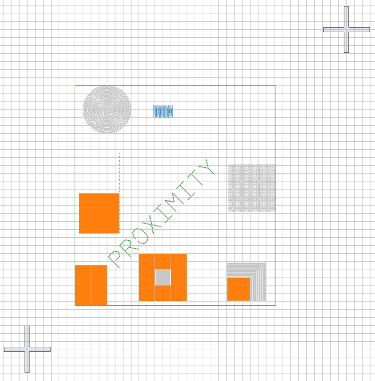
LocalMarks.yaml
size: 500
dots: 1000000
local_marks:
  - x: -50
    y: 350
  - x: 350
    y: -50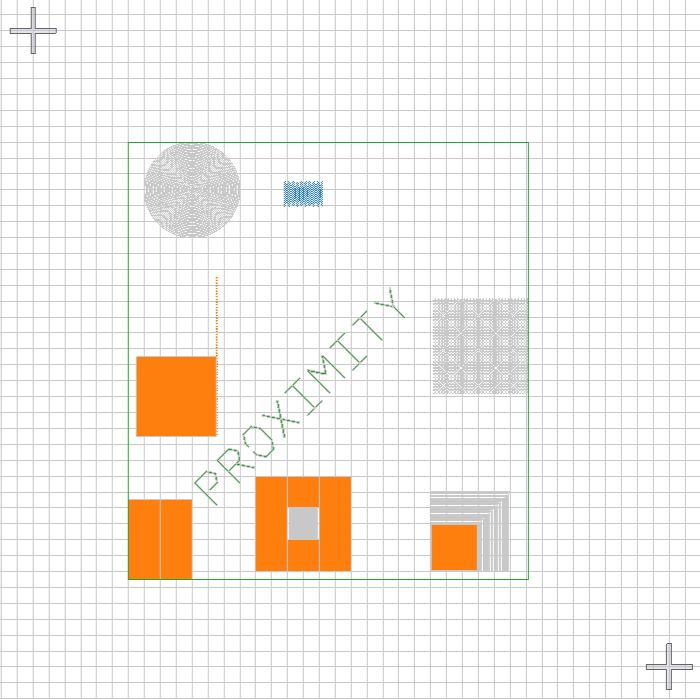
FullExample.yaml
size: 500
dots: 1000000
fields:
  - origin:
      x: 0
      y: 0
      mode:
        lattice: LowerLeft
        field: LowerLeft
    size: 300
marks:
  - x: -50
    y: -50
  - x: 350
    y: 350
local_marks:
  - x: -50
    y: 350
  - x: 350
    y: -50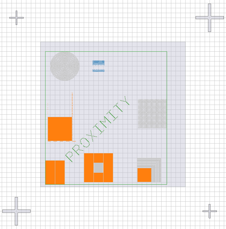
WriteField examples
FieldSingle.yaml
size: 500
dots: 1000000
origin_mode:
  lattice: LowerLeft
  field: LowerLeft
fields:
  - origin:
      x: 0
      y: 0
FieldDouble.yaml
size: 500
dots: 1000000
origin_mode:
  lattice: LowerLeft
  field: LowerLeft
fields:
  - origin:
      x: 0
      y: 0
  - origin:
      x: 500
      y: 500
FieldArray.yaml
size: 500
dots: 1000000
origin_mode:
  lattice: LowerLeft
  field: LowerLeft
fields:
  - origin:
      x: 0
      y: 0
    columns: 2
    rows: 2
FieldVectors.yaml
size: 500
dots: 1000000
origin_mode:
  lattice: LowerLeft
  field: LowerLeft
fields:
  - origin:
      x: 0
      y: 0
    columns: 2
    rows: 2
    lattice_vector_a:
      x: 200
      y: 200
    lattice_vector_b:
      x: 0
      y: 400
FieldOverlap.yaml
size: 500
dots: 1000000
origin_mode:
  lattice: LowerLeft
  field: LowerLeft
fields:
  - origin:
      x: 0
      y: 0
    columns: 2
    rows: 2
    overlap: 0.1
AutoFill examples
AutofillDefault.yaml
size: 500
dots: 1000000
fields:
  - autofill:
AutofillRegion.yaml
size: 500
dots: 1000000
fields:
  - autofill:
      region:
        size: 100
        origin:
          x: 50
          y: 50
        mode: LowerLeft
AutofillOrigin.yaml
size: 500
dots: 1000000
fields:
  - autofill:
      origin:
        x: 100
        y: 100
        mode:
          lattice: LowerLeft
          field: LowerLeft
Various examples
Origin
origin:
  x: 5.5
  y: 11.7
  mode:
    lattice: LowerLeft
    field: Center
Region
size: 1500
origin:
  x: 1000
  y: 500
mode: Center
RealPoint
point:
  x: 6.2
  y: 1.6
IntegerPoint
point:
  x: 6
  y: 1
Pitch
pitch:
  scan: 2
  feed: 3
Multipass examples
Multipass.yaml
size: 500
dots: 1000000
multipass:
  passes: 3
  shift_dist: 100
  rotation_angle: -1.04719755119
fields:
  - origin:
      x: 0
      y: 0
      mode:
        lattice: LowerLeft
        field: LowerLeft
MultipassDisabled.yaml
size: 500
dots: 1000000
multipass:
  passes: 3
  shift_dist: 100
  rotation_angle: -1.04719755119
fields:
  - origin:
      x: 0
      y: 0
      mode:
        lattice: LowerLeft
        field: LowerLeft
    multipass: false
WriteMode examples
WriteModeHorizontalScan.yaml
size: 500
dots: 1000000
write_mode:
  dir: Horizontal
  type: Scan
fields:
  - columns: 2
    rows: 2
    origin:
      x: 0
      y: 0
WriteModeVerticalSnake.yaml
size: 500
dots: 1000000
write_mode:
  dir: Vertical
  type: Snake
fields:
  - columns: 2
    rows: 2
    origin:
      x: 0
      y: 0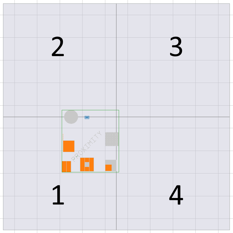
OriginMode examples
OriginModeLL_LL.yaml
size: 500
dots: 1000000
origin_mode:
  lattice: LowerLeft
  field: LowerLeft
fields:
  - size: 200
    columns: 2
    rows: 2
    origin:
      x: 0
      y: 0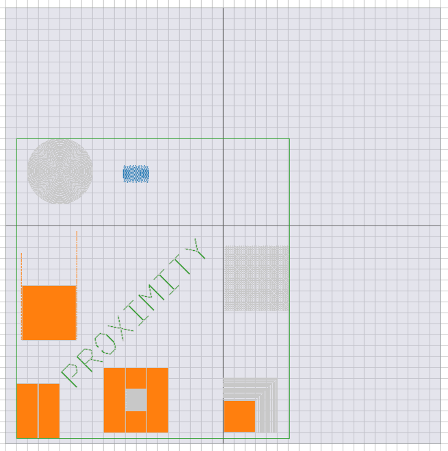
OriginModeLL_C.yaml
size: 500
dots: 1000000
origin_mode:
  lattice: LowerLeft
  field: Center
fields:
  - size: 200
    columns: 2
    rows: 2
    origin:
      x: 0
      y: 0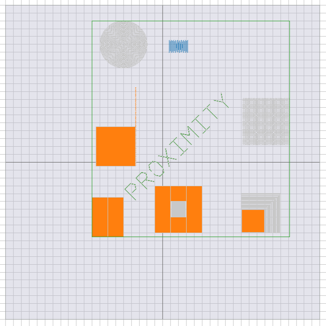
OriginModeC.yaml
size: 500
dots: 1000000
origin_mode:
  lattice: Center
fields:
  - size: 200
    columns: 2
    rows: 2
    origin:
      x: 0
      y: 0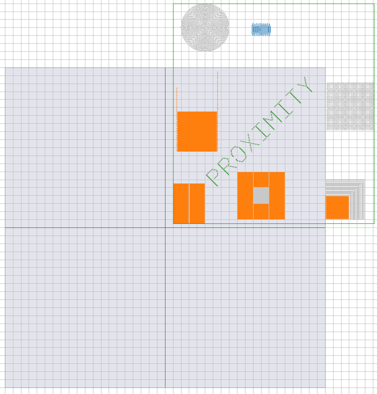
To download this documentation as a PDF, click here.